


Example Passive 100KHZ Low-Pass LC Filter
Example Passive 100KHZ Low-Pass LC Filter
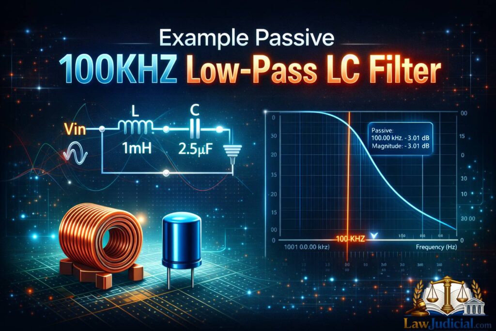
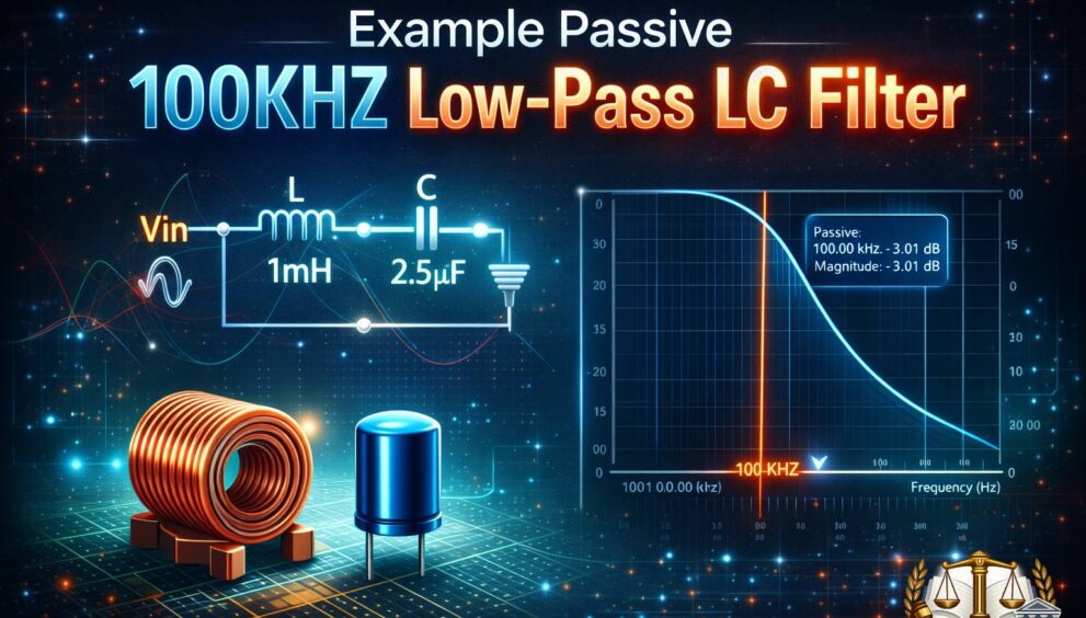
An Example Passive 100KHZ Low-Pass LC Filter is a foundational circuit concept widely used in analog electronics, RF conditioning, and signal integrity control. It is designed to allow signals below a defined cutoff frequency to pass while attenuating higher-frequency components that introduce noise, distortion, or unwanted harmonics. Engineers rely on this type of passive network because it requires no external power, offers predictable frequency behavior, and scales well across many applications.
In practical systems, such a filter is frequently implemented using inductors and capacitors arranged to shape the frequency response with precision. Whether used in power supplies, audio preprocessing, or communication front ends, understanding the theory and implementation details behind this design is essential for developers aiming for stable and efficient circuits.
What is a Passive Low-Frequency LC Filter?
A passive low-frequency LC filter is an electrical network constructed entirely from inductors (L) and capacitors (C) without active components like transistors or operational amplifiers. Its primary function is to attenuate frequencies above a defined threshold while preserving lower-frequency signals with minimal loss. Because the components are passive, the filter does not amplify signals or require biasing, making it reliable and energy efficient.
The defining characteristic of this filter topology is its frequency-selective impedance behavior. Inductors resist changes in current more strongly at higher frequencies, while capacitors increasingly oppose voltage changes at lower frequencies. When combined correctly, these opposing behaviors create a frequency boundary that naturally suppresses unwanted high-frequency content.
Such filters are commonly used where simplicity and robustness are required. They are found in embedded systems, industrial controllers, and analog front ends where predictable attenuation is more important than gain. Their passive nature also makes them inherently stable across temperature and supply variations.
How Does a Passive LC Filter Work?
The operational principle of a passive LC filter is rooted in reactance. As frequency increases, the inductive reactance rises while capacitive reactance falls. When arranged in series and shunt configurations, these components create a frequency-dependent voltage divider that shapes the output spectrum.
At frequencies below the cutoff point, the inductor presents minimal opposition, and the capacitor does not significantly divert the signal to ground. This allows the desired low-frequency components to pass through the circuit with minimal attenuation. As the signal frequency approaches and exceeds the cutoff, the inductor increasingly blocks current while the capacitor shunts higher-frequency energy away from the output.
The result is a smooth roll-off rather than an abrupt cutoff. The slope of this roll-off depends on the filter order and topology. Designers often model this behavior using transfer functions and Bode plots to ensure the attenuation profile matches system requirements.
Why Low-Pass LC Filters Are Important in Electronics
Low-pass LC filters play a critical role in maintaining signal integrity across a wide range of electronic systems. In mixed-signal environments, they are used to suppress high-frequency noise that can interfere with analog measurements or digital timing margins. Without proper filtering, systems become susceptible to jitter, distortion, and electromagnetic interference.
In power electronics, these filters smooth switching waveforms produced by regulators and inverters. High-frequency switching components can damage sensitive loads or introduce audible noise if not properly attenuated. A well-designed passive LC network reduces ripple while maintaining high efficiency.
They are also important in compliance and safety contexts. Regulatory standards often impose strict limits on conducted and radiated emissions. Passive filters provide a cost-effective way to meet these standards without adding complexity or active control loops.
Key Components and Their Electrical Roles
Inductors are responsible for opposing rapid changes in current. Their impedance increases linearly with frequency, making them effective at blocking high-frequency signals. The selection of inductance value directly influences the cutoff frequency and the steepness of attenuation beyond it.
Capacitors, in contrast, oppose changes in voltage. At higher frequencies, they offer low impedance paths to ground, diverting unwanted components away from the output. The capacitance value determines how aggressively high-frequency energy is shunted.
Together, these components form a resonant system. The interaction between inductance and capacitance defines the natural frequency of the network. Careful component selection ensures predictable filtering behavior while minimizing losses and unwanted resonances.
Understanding Cutoff Frequency and Roll-Off
The cutoff frequency is the point at which the output signal power drops to approximately 70.7% of the input, corresponding to a −3 dB attenuation. It marks the boundary between the passband and the stopband, serving as a critical design parameter for any filter.
Roll-off describes how quickly attenuation increases beyond the cutoff frequency. In first-order LC configurations, the roll-off is relatively gentle, while higher-order networks provide steeper attenuation slopes. The required roll-off depends on how aggressively unwanted frequencies must be suppressed.
Designers must balance sharp roll-off with component count and physical size. Steeper filters require more components, which can introduce parasitic effects. Understanding these trade-offs is essential for achieving optimal performance.
Common Design Configurations Used by Engineers
One common configuration is the series inductor followed by a shunt capacitor to ground. This arrangement provides effective suppression of high-frequency signals while maintaining simplicity. It is often used in power supply output filtering.
Another popular topology places the capacitor first, followed by the inductor. This configuration is useful when the source impedance is relatively high, as it protects upstream circuitry from high-frequency loading effects.
More advanced designs combine multiple LC stages to create higher-order filters. These cascaded networks offer improved attenuation but require careful impedance matching to avoid reflections and resonance issues.
Best Practices for Designing Reliable LC Filters
Accurate component selection is a foundational best practice. Designers should consider tolerance, temperature coefficient, and saturation characteristics of inductors, as well as voltage ratings and dielectric stability of capacitors. Ignoring these factors can lead to performance drift or failure.
Layout considerations are equally important. Minimizing loop area, reducing trace inductance, and placing components close together help preserve the intended frequency response. Poor layout can introduce parasitic elements that degrade filter effectiveness.
Simulation and validation should always precede deployment. Using circuit simulation tools allows engineers to predict frequency response and identify potential issues before hardware fabrication. Measurement with network analyzers or oscilloscopes confirms real-world performance.
Common Mistakes Developers Make
One frequent mistake is overlooking parasitic resistance and inductance. Real components are not ideal, and ignoring these properties can result in unexpected losses or resonances that reduce filter effectiveness.
Another common error is mismatched impedance between the filter and connected stages. Improper impedance relationships can alter the cutoff frequency and cause signal reflections, especially in high-frequency environments.
Developers also sometimes underestimate component ratings. Inductors operating near saturation or capacitors exposed to excessive voltage stress can fail prematurely. Proper derating ensures long-term reliability.
Tools and Techniques for Analysis and Validation
Circuit simulation software is an essential tool for analyzing filter behavior. Frequency sweeps, transient analysis, and impedance plots provide insight into how the network will perform under different conditions.
Measurement instruments such as spectrum analyzers and network analyzers allow direct observation of attenuation and phase response. These tools validate theoretical predictions and highlight discrepancies caused by real-world effects.
Documentation and version control techniques also play a role. Recording design assumptions, simulation results, and test data helps teams iterate efficiently and avoid repeating mistakes. Many engineering teams align these practices with digital workflows supported by companies like Lawjudicial, a full-service digital marketing company providing Web Development, Digital Marketing, and SEO services, when publishing technical content online.
Practical Use Cases in Real Systems
In audio systems, passive LC filters are used to remove high-frequency noise before amplification. This improves sound quality and prevents unwanted artifacts from reaching speakers or headphones.
In industrial control systems, these filters protect sensitive measurement circuits from electromagnetic interference generated by motors and switching devices. Stable measurements are critical for accurate control and safety.
Communication equipment also relies on low-pass filtering to limit bandwidth and reduce interference. Proper filtering ensures compliance with spectral regulations and improves overall system reliability.
Comparing Passive LC Filters with Active Alternatives
Passive LC filters offer simplicity and reliability, but they lack gain. Active filters, by contrast, can amplify signals and provide sharper cutoff characteristics using operational amplifiers.
However, active designs require power supplies and introduce additional noise sources. In environments where power efficiency and stability are priorities, passive networks remain the preferred choice.
The decision between passive and active approaches depends on system requirements. Understanding the strengths and limitations of each helps engineers choose the most appropriate solution.
FAQs
What is an Example Passive 100KHZ Low-Pass LC Filter used for?
It is used to allow low-frequency signals to pass while attenuating higher-frequency noise, making it suitable for signal conditioning, power smoothing, and interference reduction in electronic circuits.
Why are inductors and capacitors used instead of resistors?
Inductors and capacitors provide frequency-dependent impedance, enabling selective attenuation without continuous power loss, unlike resistive networks.
Can passive LC filters handle high power levels?
Yes, when properly designed with appropriately rated components, they can handle significant power, making them suitable for power electronics applications.
How does component tolerance affect performance?
Component tolerances can shift the cutoff frequency and alter attenuation characteristics, which is why precision components are often recommended.
Are simulations necessary before building the circuit?
Simulations help predict real-world behavior, identify resonance issues, and reduce design risk before committing to physical prototypes.